Serial port for the Master System
Blinking an LED is the first step with any programmable hardware, putting a serial console to work is the natural step 2. No one thought about giving the SEGA master system a serial port, so I decided someone had to do it.
Having a serial console is by far the easiest, most convenient way of interacting with a computer. It allows an easy way of controlling, monitoring, transferring information to and from a system with minimal hardware and software requirements.
The main goal of this project is to provide an UART port on an unmodified Master System so it can communicate with a PC using an of-the-shelf USB-to-UART converter.
The UART library is available as part of my Master System development ROMs repository.
Design
UART is an asynchronous serial communication method where a byte is sent/received by sending a start bit to synchronize the receiver, a number of data bits, then at least one stop bit to guarantee the receiver can detect the next start bit. At its simplest, implementing a bidirectional UART port requires one input line and one output line accessible to your software. Without dedicated hardware, the UART framing can be bit banged manually sampling the input line once an start bit is detected, and flipping the output line at regular intervals for the output communication.
Finding the RX/TX lines
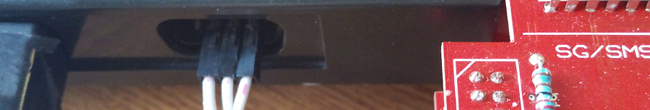
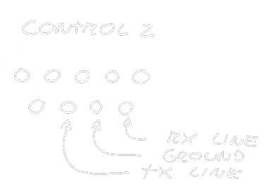
The SMS has two DB-9 peripheral ports, which are used to connect the players’ controller pads. On each port there are 5 input pins, two bidirectional pins and the two power rails. One of the bidirectional pins is not connected when using a regular pad (TH pin) so we will be using it for our output TX line; For the input line, any of the input lines would do but the bidirectional pins are ‘protected’ by a resistor in series, so we will be using the remaining bidirectional pin (TR pin) for our RX line.
The result is conveniently placed as the last three bottom pins on the player 2 peripheral port.
Transmitting data
Making the transmitter half is pretty straightforward. A register is written to flip the voltage level of the TX pin following the UART framing times, a baud rate of 4800bps was chosen since it is the fastest transfer rate that can be feasibly achieved by bit-banging the UART framing on the puny 4MHz z80 processor. A series of delay loops make the transmit side possible.
Receiving data
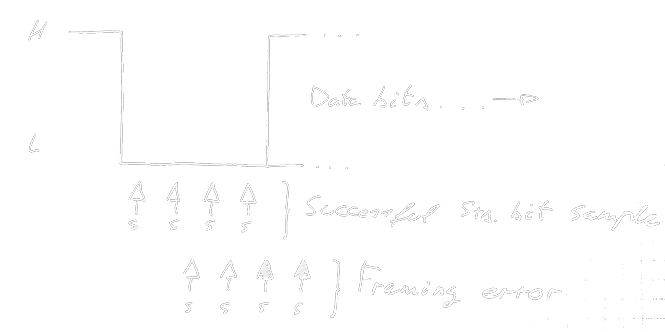
Making the receiver is not as straightforward. It is required to detect the falling edge of a start bit, sample the start bit a number of times to correctly time any future samples, and return the read byte back to the program. All of this under relatively narrow timing constraints. The basic idea is sample the start bit, returning with an error if a rising edge is detected during sampling:
Then if the start bit samples are correct, sample the input line 8 times at regular intervals, aiming for the center of each data bit using our start bit sample as a reference:
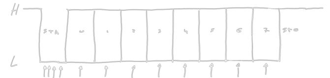
Then using our remaining time between the last data sample and the end of the stop bit to return the read byte, ready to repeat the process as soon as possible.
Implementation
Finished library is available on the software repository at the
sms/uart.c and sms/uart.h files. Examples of the library in use can be
found on the test-uart-*.c files.
Implementation of the library has been done in z80 assembler, using the SDCC calling convention so it can easily be used by C programs. The usage is documented on the header file itself.
Transmission and reception have been implemented using a series of delay loops, measured with an analyzer to match the correct UART timings, and shifting bits in and out the transmission lines. The main limitations of this implementation are that is not really full duplex (cant transmit and receive at the same time) and that reception must be polled for new data since there is no way to generate an interrupt from the peripheral port.
The delay loops have been measured to work on both PAL and NTSC, the timing differences are small enough for it not to be an issue. The bit-width throughout the code is measured in T-States, the period time of one CPU clock cycle. The bit widths (in T-States) for common baud rates are:
| Baud rate | T (PAL) | T (NTSC) | T (avg) |
|---|---|---|---|
| 1200bps | 2955 | 2982 | 2969 |
| 2400bps | 1477 | 1491 | 1484 |
| 4800bps | 738 | 745 | 742 |
| 9600bps | 369 | 372 | 371 |
4800bps was chosen because 9600 was too time constrained to be feasible and, while 4800 does not leave too much free time between bytes, it works well enough and is supported by most USB-to-UART bridges and many Bluetooth-to-UART bridges. As a ballpark number, for every 8/10 T-States we have one instruction, giving a lower limit of ~73 instructions per bit at 4800bps.
Connection to a PC
This serial port has been tested to work with a cheap CP210x USB-to-UART bridge from Silabs. Any USB-to-UART bridge should work as long as the inputs are 5V tolerant. Keep in mind the RX/TX pins internally have a series resistor of 3.3Kohm so you will have to keep that in mind if making a resistive divider, otherwise, happy hacking :)