When adding an extra wire is not an option
At my former job we developed a series of industrial control hardware that control and integrates many types of hardware which in the end are connected using either UART, RS-232 or any easily convertible-to-RS232 communication interface. A common interface is the point-to-point variant of RS485/RS422 which is easily converted back and forth to RS232 or UART with any available transceiver like the MAX3488 that has on the same 8-pin package an RS485/RS422 transmitter and a receiver. If the bus mode is half duplex or multi-drop the MAX3485 or similar is used with an additional pin to control the direction of the bus on our end.
On many, many cases our product only exposes a series of power, TTL and RS232 ports out of an enclosure, and any line-conversion is performed outside it with help of powered converters attached on these ports. If the situation requires it the converter may have a microcontroller or more often an FPGA on it doing any non-obvious protocol conversions. Now for the unexpected problem.
So a client replaces a camera…
An existing client with a fully finished product suddenly wants us to integrate a shiny new camera. No big deal, replace one serial controlled camera with the other and change the control driver we thought. It would be like that if it weren’t for the fact that the camera uses RS485 in half-duplex mode, and that no additional pin is available at all to control the direction of the bus. We in a bit out of a situation.
We cannot use an always-on transmitter since we would not be able to read the responses from the camera, but we could not control the bus since no pin is available on the existing hardware. It should also be noted we were not allowed to use microcontrollers (not in principle) out of fear of deprecation and a very large existing Verilog codebase. We would also not want to use an FPGA on this case because it is clearly overkill although we would have used it as a last resort in the event a solution was not found.
…and dirt-old hardware saves the day
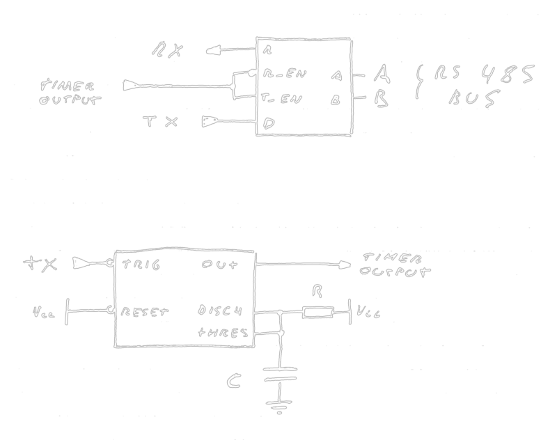
The problem is, essentially, keeping the transceiver transmit signal active for the time required to complete a command from Control to Camera then immediately relinquish control of the bus as to get the feedback, this without an extra line from the control hardware and, as tested with a scope, at most a couple bits of separation between the command request and the camera response.
By attaching a timer to the transmit enable signal, we can keep it up for the time span of 9 to 10 bits, at which point we could release the bus and let it float back up to a high value since at that time we are on the high “stop” bit of the transmission. Also, because all byte transmissions start with a low “start” bit we have a convenient trigger to launch a timer.
This looks like a very direct application of the 555 timer where R/C are tuned for the duration of 9.5 bits with 0.5 bits of margin of error, the output is connected to the transceiver transmit enable signal, and the trigger is the UART transmit line itself, which will trigger the timer on a falling edge which will always exist at the start of a byte transmission.
Result
We sourced the circuits, choosing a modern CMOS variation of the 555 timer, the ICM7555 and the MAX3485 RS485 half-duplex transceiver. The final board also has an optional transceiver MAX3232 for the cases where RS232 is used instead of UART.
The core of the solution is as follows:
The venerable 555 timer keeps being useful 47 years after its release.