Making a Roland mill understand g-code.
It is time to document one of my older projects, which I finished on a working state around ~5 years ago. The project in question makes an old Roland EGX-30 engraver accept a reasonable subset the very common machining language ‘g-code’ so it can be used for interesting tasks like milling PCBs.
Project source code available on source code repo. egxmake is the tool
described on this post.
Motivation
At my University there was available an electronics workshop with most tools you would need to design, test and make electronics projects, stuff like discrete components, breadboards, scopes, logic analyzers and more. Among the tools there was “the” disappointment, a desktop engraver purchased with the promise of being able to mill PCBs but in the end the available software was just not enough nor precise enough to make circuit boards even though the machine itself was more than capable for the task.
The electronics department head at the time essentially gave me open access to the lab to “do as I please” under the promise of making that machine mill printed circuit boards once and for all.
…Challenge accepted!
The machine itself
The machine was a Roland EGX-30 desktop engraver, a 2.5 axis CNC mill with a parallel port and a serial port connection. The target use cases are plastic engraving and cutting.
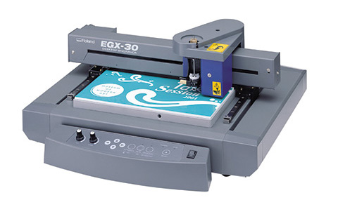
The X/Y axis have a decent tenth of millimeter error but the Z axis full-up or full-down, hence the 2.5 axis concept.Toll can either be a rotary tool or a non-rotary scoring head (diamond cutter) with a mode selection on the machine.
The machining language
Unlike most recent mills, the EGX-30 does not understand g-code, instead it uses a subset of the CAMM-GL instruction set, these instructions allows to configure some aspects of the machine like axis-speed and spin-up times, and of course it allows moving the tool around and lifting/downing the machining tool.
CAMM-GL and g-code are pretty similar, with the caveat of this machine only supporting 2.5 axis and that most of the CAMM-GL commands will actually make the machine just stop. Roughly, the command mapping looks as follows.
| Description | CAMM-GL | g-code |
|---|---|---|
| Tool down | PD |
G00 (positive Y) |
| Tool up | PU |
G00 (negative Y) |
| Position tool (raised) | PU |
G00 G01 |
| Mill path | PD |
G04 G01 |
| Tool RPM | [none] | Sxx |
| Feed rate/Linear speed | VS |
G01 (F argument) |
Making a translator for this should be easy, right?
Recompiling g-code into CAMM-GL
While a quick program was set up using regex parsing, the result was not robust at all. Valid g-code programs would crash the translation process so it was decided a proper parser shall be built. The result was a python program implementing a recursive descent parser of g-code, which allows converting commands with arbitrary argument lengths and conveniently ignoring any unknown tokens if found.
The result
The resulting program allowed me to get a Gerber file set, convert it to g-code using pcb2gcode then use my own recompiler to convert the g-code into CAMM-GL so it can be fed to the EGX-30 engraver.
The following video, recorded with a cheap cam is the only remaining good enough video of the milling process using files generated by this recompiler. Pardon the sub-par video quality and the speed-up.